
J. Parlour & Son
Anaerobic Digester and Fercell Bowmatic Rotacrex Waste recycling mill Repairs and Maintenance, also Parts and Equipment Design and Manufacture.
South Otterington, Northallerton, North Yorkshire, DL7 9HJ, United Kingdom.
We are currently in the process of a major reconstruction of the firm. Two of our team are over or approaching 70 and the younger ones are only interested in Anaerobic Digester and Rotorcrex work. All our farm machinery except a telehandler has now been sold. We reserve the right to decline other services although it's always nice to see visitors. Because of lots of good feedback about useful info on our website we are leaving open several sections just in case there's anything useful. Please also note that two of our phone numbers have changed.
John, mob: 07788 725871, home: 01325 651086.
Email: johnparlour07@gmail.com
Head of AD work, Sven 07582 737469,
Email: svenharker1983@hotmail.com
Kuhn Power Harrow Maintainance Tips
On this page:
1. Bed lubrication.
2. Packer bearing maintenance.
3. Ingress of water into bed and gearbox.
4. Bed repairs.
5. Centre shaft falling out.
6. Rotor bearings.
7. Rotor timing.
8. Slip clutch.
All the below info applies to the Kuhn 3002 and 4002 power harrows also some of the folding ones with the same beds and some other models.
1. Bed lubrication.
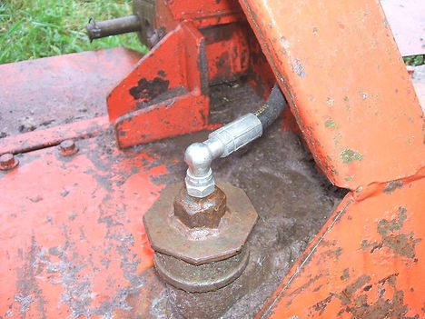
We find the Kuhn Power harrow to be very good, but nothing's perfect and one fault we've discovered with the Kuhn is no grease filler in the bed. Apparently Kuhn designers expected these machines never to leak, however we've discovered this is not the case.
In order to fit a filler hole, see photo above, you will need a hole saw around 40mm, some 2 inch water pipe fittings and a welder. The bed grease level needs to be about half way up the gear teeth so it's best to drill the hole directly over the teeth of one of the gears but not where the gears mesh because it will be difficult to see the level at that position. Measure the centre to centre distance between two adjacent rotors and divide by 2 which will give you the radius of the gears. Chose a position for the hole, not too far from the left to right centre of the bed, then drill the hole, maybe 80 or 100mm in front or behind the forward to back centre of the bed, one radius distance from the centre of the chosen gear i.e. over the teeth of the gear. Be very careful not to drop the plug into the bed. Stop drilling before breaking through and then remove the swarf and prise out the plug. Minimise the swarf entering the bed. Fabricate a filler cap as required and weld it around the hole just made. You might also provide a breather, while you're on the job, with a piece of pipe or hose from your new filler cap to a region of minimum dust, see below and photo above. For safety, do not run the machine while topping up, but you will need to run it after topping up, in order to level out the grease, and then check the level again. If your machine is fold up you will need to run it for a minute or two before checking the grease level and in order to maintain correct grease distribution always unfold when parked. For more info please ring 01609 773607 and ask for John Parlour.
2. Packer Bearing Maintenance.
Frequent greasing of the packer bearings is essential because the grease will help to flush soil out of the dust covers. All ways pump grease in until it oozes out of the dust covers. Periodically check for wear of these bearings because if wear is rectified in time money can be saved. To check for wear, lift the machine off the ground then place a crow bar under the flange on the end of the roller then push down against the arm in order to lift the roller, if there is 2mm or more of movement then replace the bearings. Replacing bearings at this stage may avoid the need to replace the housing and dust covers thus saving money, also if the roller is free to move in the bearings, it is impossible to set the scrapers correctly and may result in excess wear of the roller due to it scraping on the scrapers. Your local bearing stockist will normally keep these bearings but it's essential to get the correct ones as some unsuitable ones will fit. Just quote these numbers and your bearing dealer will know what you want, UC308 or SBX0852. We stock these bearings. The only difficulty in changing these bearings is that you need a special socket to remove the nut on the end of the stub axle, you could borrow ours if you like. Pics and more tips to follow when I get chance.
3. Ingress of water into Kuhn power harrow bed and gear box
We have heard that Kuhn power harrows will take in water when left out in the rain. We have also seen evidence of this when going inside them in the form of rusty gears and bearings. We now keep ours under cover over winter.
We recently experienced a problem with one of ours and also a customers machine leaking bed grease from under the gear box. We decided that this may be due to water in the bed evaporating when being heated during work and thus building up pressure in the bed and blowing out the grease. Changing the grease in one of these machines is a major operation so we decided to fit a breather in order to relieve the pressure. In both cases the leakage stopped. Our machine already had a grease filler point so we drilled a hole in it, attached a pipe to run up inside the A frame to a region of less dust and with the pipe end facing down to help prevent dust falling in. Not shown in the picture. Of course this doesn't address the problem of rusty gears and bearings. Since fitting these breathers I've heard that this leakage can be caused by over filling the bed with grease and maybe nothing to do with water in the bed, however the breather did stop the leak.
4. Bed Repairs
Bed repairs on these machines aren't difficult but most are time consuming. The rotor seals can be replaced from below but it's critical to get the correct seal and fit it correctly see 'Centre shaft falling out' below or we can advise.
A common problem is the bottom of the rotor bearing housing wearing away due to string and wire wrapping around the rotors. This can be rectified without a major strip down. What we do is weld a piece of hydraulic ram tube to the bottom of the housing, or you can make a collar on a lathe, the ram tube we use is 90mm id x 110mm od. It's not a popular size but A5 Hydraulics, Darlington, ask for Nick, has always come up with the goods, or we might have some on stock. Warning, welding can cause contraction thus causing nipping of the bearings, it is possible to keep the welding away from critical areas, we can advise. The rotors are easily removed but the timing isn't obvious, see below. When refitting, keep the splines and tapers clean and dry, Loctite the M16 bolt and tighten to 221 lbs / ft.
Most other bed repairs, including replacing rotor bearings, will require a major strip down. Replacing rotor bearings requires removing the lid from the bed then remove the relevant cogs so as to expose the bolts holding the bearing housings in place then remove these bolts and housings. Don't mix up the parts. The reason for removing the housing is so as to check the bearing preload on re assembly. Further info to follow. On final reassembly the m36 x 1.5 nut needs to be Loctited and torqued to 450 lbs / ft. Click here for more torque settings. This paragraph still under construction, March 2020.
5. Centre shaft falling out.
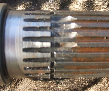
It has been known for the vertical drive shaft from the gearbox to the bed to fall out. This is caused by failure of the circlip. Earlier models use a thinner circlip, I believe, 2mm thick. The later ones are, I believe, 3mm thick. This thicker circlip requires a larger groove in the shaft and a thinner spacer in order to allow space for the thicker circlip. Since publishing this info I have found a thin circlip in a large grove so the previous sentence may not be true. Also the splines just above the circlip can crumble thus putting more stress on the circlip, see picture above. The later parts fit the earlier machines so long as you replace all three parts together, shaft. circlip, spacer, but bare in mind there are two different rotor splines I know of, and check the grove width in your old shaft before ordering a new one. Replacement of these parts requires the bed top to be removed. When reassembling it is important to use the correct rotor oil seal and to press it in to the correct position, same with all the other rota seals. You will need a seal press / gauge, this device is easy to make if you have a lathe. Ring me if you need more info, or you could borrow ours. The seal is double lipped, metal cased, no. 65-90-13 R6, available from your local bearing stockist, cheaper than genuine, but be careful they might try to fob to off with something else. It's important to get the correct parts. See 'Bed repairs' above above for refitting the rotor.
Follow this advice entirely at your own discretion, I accept no responsibility for any loss, damage, death or injury due to following this advice.
If you know anyone you think might find this useful please feel free to copy and email it to them. Please include this URL. www.jparlourandson.co.uk
6. Rotor bearings
If you find any more than a very small amount of play on the rotor bearings they will need to be replaced. Be careful when checking because loose rotors can be mistaken for loose bearings and a loose rotor can be vastly easier to rectify. The job is quite simple but a lot of work because the bearing housing needs to come out and the retaining bolts can only be accessed from inside the bed. It's pretty obvious how to remove the bed top. Then remove the cog/s above the offending bearings. Remember you will need to retain the correct timing or re time on assembly, see below. You will need a special socket to fit the nut. It needs to be a socket and not a wrench because the nut needs to be torqued up on refitting and the torque is 450 lbs/ft so you will need to be careful not to damage anything when jamming the rotors in order to turn the nut. Your Kuhn dealer can supply a socket but they're expensive, or you can make one but it's a fiddly job. Under the cog you will find some m12 bolt heads, 19mm AF, remove these and the housing will come out. Take the assembly to the bench and dismantle. Thoroughly clean the bearing housing and new bearings. Check the bores for the bearings and seal. Another common problem is the bottom of the housing wearing away so check this now, see 'bed repairs above'. Use Locktite when fitting the new outer races to the housing and make sure they are pressed in quite hard before the Locktite setts. Now fit the inner races, Locktite optional. Check that the bearings are still clean and apply some light oil. You will then need to reassemble, on the bench, the bearing housing, shaft, cog, spacer and nut, without the seal, in order to check the preload on the bearings. You might chose to loosely fit the rotor in order to hold the assembly while partially torquing the nut. Torque the nut to 300 lbs/ft, don't use a cast iron vice to hold the assembly while torquing, it might break. Now grip the assembly in a vice in such a way as to allow the bearing housing to spin freely. Mark a point on the bearing housing and spin it as fast as you can by hand, it should stop in about one and a half revolutions. If it's less you need a bigger spacer, if it's more you need a smaller one. Repeat until correct but don't worry, most of the time the original spacer is ok. You can't measure the spacers with calipers, vernier or micrometer because the top and bottom faces aren't directly opposite, you need a surface plate and height gauge and a couple of thou makes a big difference. Disassemble the sub assembly and re assemble in the bed without the seal. Use O rings and silicone to seal the housing to the bed. check that the M12 bolts and the holes they fit into are clean and Locktite them and torque to 78 ft/lbs. These m12 bolts have been known to come loose when used on stoney ground so be careful. Make sure the M36 x 1.5 nut and shaft are clean and Locktite it and torque to 450 ft/lbs. Now you can fit the seal, there's no face for the seal to but up to so its important to press it in the correct amount and perpendicular with the bore, see 'Centre shaft falling out above'. For refitting the rotor see 'Bed repairs above'.
7. Rotor timing
See photo below, I included this to help illustrate how to time the rotors. This machine is a little out but it's near enough. See the rotor at the left (clockwise rotating from where we're looking) the blade bolts at the top are directly above the ones below. Let's call this position, 12 o'clock. Now see the rotor next but one to it (the next one rotating the same direction) this one should be at 11 o'clock and the next but one from that should be 10 o'clock and so on to the end. Now go back to the left and repete, except starting with the next but one from the end (the first anticlockwise one) turn it until the ones on either side are 17.5 minutes to and 17.5 minutes past, now this one (the next but one from the left) should be at 12 o'clock if it's not then turn it on its splines to 12 o'clock and now the next but one from that to 1 o'clock and the next but one again to 2 o'clock and so on. Now since it's probably impossible to get it spot on, unless you go inside the bed and retime the cogs, check every rotor by setting it to 12 o'clock and the ones on either side should be 17.5 minutes to and 17.5 minutes past. Some models have an odd number of splines in the rotors so if you can't get it quite right remove the rotor and rotate it a little more or a little less than 180 degrees, this doesn't work with an even number of splines. For refitting the rotors see 'Bed repairs above'. The reason for this timing is, I believe, to reduce stress by not having several blades all hitting the working front at the same time.

8. Slip Clutch, Plunger Type
The setting range between the outer faces of the spring tensioning nuts is 129 to 123mm. During assembly lubricate the clutch with EP2 grease, or similar. Remember we're talking about the plunger clutch only. More info when I get chance.

The above info is correct to the best of my knowledge but I'm certainly far from infullable. Take all this at your own discretion. I accept no responsibility for any loss or damage you might incur. I always say to my lads "Don't copy other peoples mistakes". Please feel free to contact me, I beleive they say "talk is cheap".