
J. Parlour & Son
Anaerobic Digester and Fercell Bowmatic Rotacrex Waste recycling mill Repairs and Maintenance, also Parts and Equipment Design and Manufacture.
South Otterington, Northallerton, North Yorkshire, DL7 9HJ, United Kingdom.
We are currently in the process of a major reconstruction of the firm. Two of our team are over or approaching 70 and the younger ones are only interested in Anaerobic Digester and Rotorcrex work. All our farm machinery except a telehandler has now been sold. We reserve the right to decline other services although it's always nice to see visitors. Because of lots of good feedback about useful info on our website we are leaving open several sections just in case there's anything useful. Please also note that two of our phone numbers have changed.
John, mob: 07788 725871, home: 01325 651086.
Email: johnparlour07@gmail.com
Head of AD work, Sven 07582 737469,
Email: svenharker1983@hotmail.com
Tips for Muck Spreader Maintenance and Parts Identification
On this page
1. Tips for Bunning and ECE bed drive maintenance.
2. Bed drive gearbox bearings.
3. Bed drive relief valve setting.
4. Check bed chain for wear.
5. Tips for fitting Bunning auger gearbox to ECE spreader.
6. Better sealing for ECE auger gearboxes.
7. Tips for identifying parts.
1. BUNNING / ECE BED DRIVE
The gear box can be difficult to remove but not always, some machines have the shaft diameter reduced in order to facilitate removal. Because of this difficulty we try to do as much of our maintenance as possible without separating gearbox and shaft. Don’t be tempted to apply force to the gearbox casing, it will break. The whole gearbox / shaft assembly can be removed, by removing the bush housing bolts and sliding the whole lot out through the bush housing hole. If you are unlucky enough to break the gearbox casing we may be able to supply a second hand one.
The easiest way to remove the sprockets is with a burning torch, but be careful these shafts are alloy steel and under considerable stress when working. High temperature can affect the temper of the shaft.
If the shaft is to be replaced just cut it and use a press to remove the stub from the gear box taking care not to put any force on the gearbox casing. We use a 50 ton press and on occasion even that has failed to separate gearbox and shaft in which case remove the hub / sleeve from the gearbox with shaft still in it and apply heat while pressing, see photo below. Note the steel plate between the end of the shaft and the press ram, this is to protect the ram from the heat.
Another way to remove the gear box is to make a puller from a short piece of suitable size steel pipe, weld a nut, at least m40, in one end with its axis in line with the tube axis, weld the tube and nut to the gearbox hub so that a piece of threaded bar screwed through the nut will bear on the end of the shaft, take a piece of suitable size threaded bar, weld a nut to one end and screw it through the nut welded to the gearbox hub. Be careful not to get weld splatter in the gearbox. Separating the hub and shaft can require a lot of force, sometimes more than 50 ton, so a substantial nut and screw is essential, even then it doesn't always work, and remember you will need to clean up the gearbox hub after cutting off the tube. You could also remove the sprockets by this method but remember there is a grub screw between the flanges of the sprockets.

If the slopey bit on the side of the gearbox is facing in over, like an ECE, it is possible to draw the gearbox off its hub leaving the hub on the shaft. See pic below, this gearbox will remove by this method. You will need to remove the entire gearbox and shaft assembly. Before removing the gearbox from it's hub remove the rectangular plate on the gearbox and look inside, then it will be obvious which way the hub moves relative to the gearbox. Then remove the inner seal and sir clip and draw the gearbox off its hub. And / or click here and scroll down to page 26 for an exploded view of the gearbox. In this image the hub moves to the left for removal. On some other makes of spreader you may be able to get to this sir clip without having to remove the assembly first. The hub can then be removed from the shaft as above but you now have the option of using a little heat but remember the shaft is tempered, so too much heat will affect this. Another way to remove the hub is to use a 50 ton, or more, conventional workshop press, but you will need to lift the press in order to allow the shaft to protrude from beneath, see photo, and notice the steel plate laid on top of the shaft to keep the heat away from the press ram. Be careful, I accept no responsibility for any one dropping a press on themselves, or any other kind of accident. You may also need to remove the sprockets to get the shaft into a press. This method can be used for a gear box with slopey bit on the outside but the gear box will need to come over the entire length of the shaft requiring the sprockets removed first. When refitting make sure the gearbox slides on easily, grease the shaft and hub to make the job easier next time.

Whether or not you separate the shaft and box always fit new double lipped seals to the gearbox because muck can squeeze through the bush, through the seal and damage the bearing. While the seals are out check the bearings. These bearings do fail and then cause other damage.
If fitting new sprockets with the gear box on the shaft then grind the rust off the shaft in order to allow the sprockets to slide easily but avoiding the bits where the sprockets fit, use Loctite when refitting. While you're at it, fit a new double lipped seal in the back side of the gear box.
Regularly check all the gearbox oil levels and oil colour and change if discoloured.
2. BED DRIVE GEARBOX BEARINGS.
One problem with both Bunning and ECE spreaders is muck getting through the rear bed shaft bush and thence through the gearbox seal and damaging the bearing. I can't remember a failure of one of these gearboxes which wasn't initiated by bearing failure, but not always due to the above problem. We often replace bearings and seals before failure occurs. We are experimenting with different bearings like angular contact and cylindrical rollers but these cost a lot more and won't solve the muck problem, however we believe the extra cost may be worth it and we always grease this bush frequently. We are also thinking of ways of reducing the muck problem. Please feel free to contact us for more info 07788 725871 or watch this space, I'll provide more info here when I get chance.
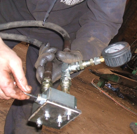
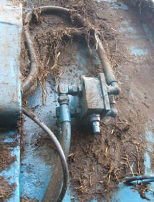
The older Bunning and ECE spreaders had only a single relief valve on the bed drive thus extensive damage can be caused if the bed is run the wrong way when the spreader is full. We recommend the fitting of double relief valves especially if you are hiring out.
It is important to set these relief valves correctly. Different sizes of spreader and different sizes of motor may need different pressures. Bunning's recommended pressures for their 2014 Lowlander 120 Mk 4 are 2000 psi for empting and 1000 psi for reverse. These valves can be set prior to fitting by connecting them to a tractor hydraulic output. You will need 2 suitable hydraulic hoses, a T piece, a pressure gauge and a blanking plate.
All items are readily available from us or elsewhere, the blanking plate is easily made, just a flat piece of 8mm or thicker plate with 4 bolt holes drilled in it.
Some models of motor won't accept this relief valve. There are numerous valves available but what we do is put one of the same valves in the line, however the motor side of the valve has no threads in the ports, so a suitable adaptor plate will need to be fabricated. We could do this for you or you could do your own, it is not difficult, see the right hand picture.
We accept no responsibility for any loss or damage caused by following this advice
4 Check bed chain for wear.
You can check the wear on your bed chain by measuring the pitch. It's difficult to get an accurate measurement by just measuring 1 link so measure 10, see pic, and it's a little difficult to decide exactly where to measure from / to so count the links between the 2 chalk marks in the photo and mark yours likewise. The chain needs to be under normal tension, then measure the distance between the same point on the 2 links, maybe the front end of both, see red lines on photo. Remember it's the pitch your measuring and not the overall length of the 10 links. The old type chain is well worn at 510mm and new type at 540mm. I have, on occasions, known them go a bit longer than this. Please note, chains this worn won't run correctly on new sprockets except maybe old type chain at 510mm on new type sprockets. It is possible to build up old or even new sprockets with weld to fit worn chains but a bit tricky to get rite. We haven't built up sprockets for many years now. To identify which chain you have the overall length of each link is 77mm old and 80mm new, bear in mind these chains aren't accurate even when new. I'll add more info when I get chance.
We spray our chains with oil while out of season, if we can get around to it, the chain on the right is sprayed.

5. Instructions for fitting Bunning gearbox to ECE spreader.
Don’t assemble the couplings yet. First try the top part of the coupling in the bottom of the rotor. If the teeth in the bottom of the rotor are burred the burs may need to be ground off.
Note: after assembly there will only be limited scope for altering the rotor timing. The rotors are on 8 spline shafts so the minimum easy alteration of timing is 1/8 of a revolution. Or you could separate the rubber couplings and gain another 3 positions giving 24 in total but a bit fiddly. If you consider this to be sufficient then skip the procedure in the next paragraph but read it anyway.

2. You might prefer to set the timing before welding the couplings in. If so I suggest that you first insert the inner halves of the couplings into the outer halves without the rubbers, insuring correct alignment and timing. You could mark the outside of the two halves in order to position them correctly then lightly tack weld the two halves together. Place the couplings onto the output shafts of the gear box. Turn the rotors until the required timing is obtained. Please note, when setting the timing consider the auger flighting, ie. position the flighting on one auger approximately, vertically half way between the flights on the other then check the auger teeth (stripers) spacing them as far apart as possible then, most important, the paddles on the bottom of the rotors. We find there is no perfect timing. Raise the gear box assembly into position and re check the timing. Check that the couplings are parallel with the augers, check that the bolt pattern on the end of the gearbox is aligned with the channel section it bolts too. Weld the top part of the couplings to the rotors, remove the gearbox, grind the tack welds off in order to separate the couplings and remove the lower part of the couplings. This method gives the best timing but if you chose to leave the timing until later then skip this paragraph.
Another alternative would be to use the above procedure except assemble the couplings c/w rubbers and weld to the augers with the rubbers already inside, but you would need to be very careful not to burn the rubbers, you would need to weld a tiny bit and then allow cooling before proceeding further.
If you have skipped paragraph 2 then insert the top part of the couplings into the rotors, carefully check alignment and weld into place. Note: the rubbers have some of the corners chamfered in order clear the welds on the blades of the two parts of the coupling. These couplings aren’t desperately tight fitting so you shouldn’t have a problem squeezing them together however you might chose to provide a slight chamfer on the ends of the blades and / or use washing up liquid to ease the rubbers in, do not use lubricating oil. Position the lower part of the couplings, complete with rubbers beneath the upper part and squeeze fully into place with a jack. Bear in mind the rotors aren’t vertical so the jack will need to be tilted also the spreader prevented from rolling. Note: the bearings on the tops of the rotors are housed in cast iron so can’t take a lot of force. Grease the splines of the couplings and gearbox. Maneuver the gearbox into position and engage the splines, check the timing, then, assuming the auger top bearings allow, raise the gearbox until it has lifted the rotors about 8mm off the deck, check the couplings and splines are fully engaged, check that the bolt holes in the end of the gearbox are aligned and central with the channel sections on the back of the spreader ie. the two front and back holes are parallel with the edges of the channel, check that the ends of the gearbox are the same height relative to the spreader, check that the rotors turn freely and are not catching anywhere, then mark and drill the holes. You may need to remove the gearbox to drill the holes then bolt the gearbox in place. You will find that the gearbox overhangs the bottom of the spreader so take a suitable size piece of flat bar or plate, longer than the diameter of the gearbox so that you can get some weld on the inside, drill two holes in it, bolt it to the end of the gearbox and weld it to the spreader. See bottom left of the photo below. Don’t burn the rubber seal in the end of the gearbox.
You will need to change the UJ yoke on the input shaft because the new gearbox has a bigger spline. Your local Agricultural Engineer should be able to supply anything not in the kit. This yoke normally incorporates an over run clutch. We remove these clutches from our spreaders because doing so reduces the frequency of shear bolt breakages. If you want to keep your overrun clutch you could reverse this shaft so that the clutch is at the front of the shaft further forward under the spreader then you only need to swap the plain yoke for another plain one with a bigger spline.

Use this info at your discretion. I accept no responsibility for any problems you may incur by using any of the above info.
6. Better sealing available for ECE muck spreader auger gear boxes.
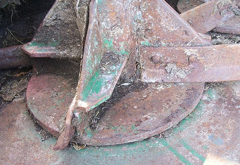
There is a tendency for muck to fall through the hole in the auger deck and thence through the seal and into the gearbox, see the photos below. There is now a seal available which attaches to the bottom of the auger drive dog which is a big improvement but still not perfect. The later dogs have a shoulder on the bottom for the seal to attach to. It's not difficult to reproduce this shoulder if you have a lathe, just weld a suitable size washer to the bottom of the dog and then turn to size. We can advise 07788 725871. With or without these seals it is very important to check the gear box oil level and color frequently and top up or change as required. Make sure these dogs are well greased during assembly and have a good o ring in place, the o ring can be seen in the first pic. Scroll down for another way to reduce the muck in gearbox problem.
Just to prove what I'm saying about ingress of muck, see first photo. I hasten to add, this gearbox isn't from one of our spreaders. The second photo shows a new type dog on a gear box with seal fitted. Next is a new type dog with seal fitted and an old type dog. Next is a new type showing the shoulder and the last picture is, left to right, new type, new type with seal and old type. We are constantly working on improving ours and customers equipment. If you would like any further advice please ring John, number at top of this page. Click here for price of these dogs and other parts.
We accept no responsibility for any problems you may incur by following this advice.


See right, another way to help reduce the muck entering the gearboxes. This also greatly increases the strength of the paddles. It is a 10mm thick steel disc welded to the bottom of the auger although 8mm should be adequate. It's possible to fit these with augers in situe, just cut the disc in half and weld it back together while welding it to the auger. This one has a ring made from 8mm round bar welded to the underside of the periphery of the disc and another smaller one welded to the auger deck under the disc. You will need to burn off the original very small disc and maybe a bit off the bottom of the paddle brackets. Note: this isn't a substitute for the seals shown above. Take this info at your own discretion, I accept no responsibility for any loss or damage you might incur by following this advice.
7. Tips for identifying parts.

There's usually very little problem identifying the correct parts except for ECE auger drive gearbox parts. Up to now, I believe we've identified 10 different auger gearboxes and 9 different center gearboxes. This info is not yet complete.
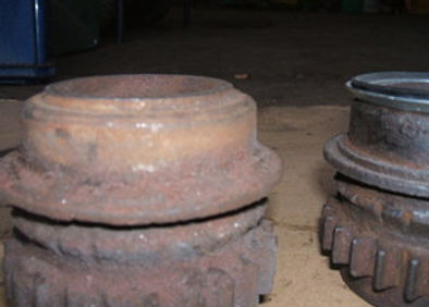
The three photos on the right are ECE auger gearbox crown wheals. The problem here is that there are two different cogs both with 27 teeth. In all these photos the ones on the left are the same and for 540 RPM PTO and all the ones on the right are the same and for 1000 RPM PTO. They are not interchangeable. See the top photo, the bevel is a different angle. We have recently discovered one with 28 teeth.

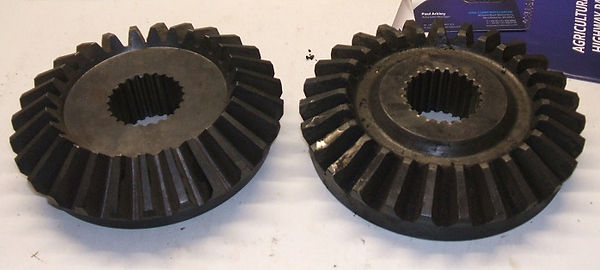
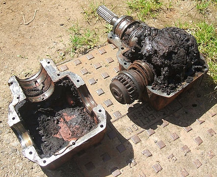
These 2 gearboxes are just 2 of the 10 different ECE auger gearboxes we know of so far. The top one is one of the four second oldest types, no longer available. The bottom one is one of the four new types which will directly replace the second oldest ones. The very oldest is still available but not directly interchangeable with the later ones. The four new types are:-
540 RPM PTO with 6 spline input shaft, 1.5 to 1 ratio.
540 RPM PTO with 20 spline input shaft, 1.5 to 1 ratio.
1000 RPM PTO with 6 spline input shaft, 2.08 to 1 ratio.
1000 RPM PTO with 20 spline input shaft, 2.08 to 1 ratio.
The ratio is sometimes marked on the identification plate. The 1000 PTO ones have 27 tooth crown wheel and 13 tooth pinion. The 540 PTO ones have 27 tooth crown wheel and 18 tooth pinion or so I believe, or maybe you can prove me wrong, I wouldn't be surprised. The very oldest are same as 540 PTO Bunning mk one. With the help of a customer from Orkney I recently discovered the 10th different gear box which is: 16 - 28 teeth, 1.75 to 1 ratio but that's all I know about this gearbox so far. Click here and go to the bottom of the page to see our left over stock.


This pinion is for ECE auger gearbox, 1000 RPM PTO, 6 spline shaft, 13 teeth, the same pinion is available with 20 spline shaft. Some pinions are splined to the shaft and thus can be separated from the shaft. The 540 RPM pinions have 18 teeth. I recently (April 22) discovered a pinion with 16 teeth. This 16t pinion is splined to the shaft and runs with a 28 tooth crown wheel.

Bed drive bushes. Click here for help to identify these bushes.
